
amixon® helps with the dimensioning of large vacuum mixer dryer systems
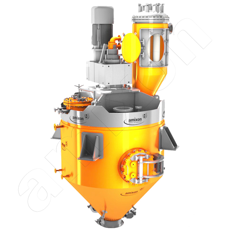
amixon® vacuum mixing dryers and synthesis reactors are used for almost all types of bulk solids and suspensions. Due to the large specific heat transfer surfaces, amixon® devices are also used as evaporators.
The compact amixon® vacuum dryers are characterized by the following properties:
- outstanding energy efficiency
- very gentle product movement
- large specific heat transfer surface
- very high drying speed
- gentle drying due to targeted vacuum setting
- ideal mixing quality
- particularly hygienic design
- amixon® apparatuses are also used as sterile reactors in the biochemical and pharmaceutical industries.
How can amixon® help with the transfer of laboratory results to technical scale?
When new products or processes are developed, questions of technical implementation must be examined in parallel. Scaling up from a test tube to an industrial plant is not trivial.
The pilot plant is used to define process parameters that lead to similarly good results as those previously achieved by the researchers in the test tube.
amixon® is a manufacturer of process engineering systems and has its own pilot plants. The systems there are fully functional. They are dimensioned in such a way that they can be used to design large-scale industrial plants.
Practically all bulk material mixing/refining and vacuum drying processes can be demonstrated with amixon® in the technical center. The pressure in the mixing chamber can be varied from 5 mbar to 26 bar (absolute pressure). The temperature can be varied from sub-zero to 350°C.
This allows customers to quickly find out how well and quickly a synthesis reaction or vacuum drying process works with their product.
How do you extrapolate from a pilot plant to a large-scale plant?
Difficulties arise when the industrial plant to be set up is 100 times larger than the process machine in the pilot plant. For thermokinetic issues, geometric similarity considerations fail. Practical know-how in the application of thermodynamic calculations helps here.
amixon® helps with extrapolation to process machines that are many times larger than the test plant. The accuracy of our calculation methods has been proven time and time again by amixon®. Namely, whenever the large-scale system in the industrial environment achieves or exceeds the calculated performance.
amixon® is happy to invite customers from near and far to take part in trials and promises them very good results in advance. We can do this thanks to decades of experience.
Drying tests in the amixon® technical center are always target-oriented and provide a high level of knowledge. amixon® protects the information shared with you from third parties. This means that the exchange of information always remains confidential.
Drying tests differ from classic mixing tests. The process time is considerably longer. A lot of data is recorded during the drying process in the amixon® technical center. This is largely automated.
This leaves enough time to discuss constructive details. A detailed factory tour should always take place. Some customers use the time to carry out mixing tests for the subsequent process. Others use the time for agglomeration tests.
How can the flow of powders in an amixon® vertical mixer be calculated?
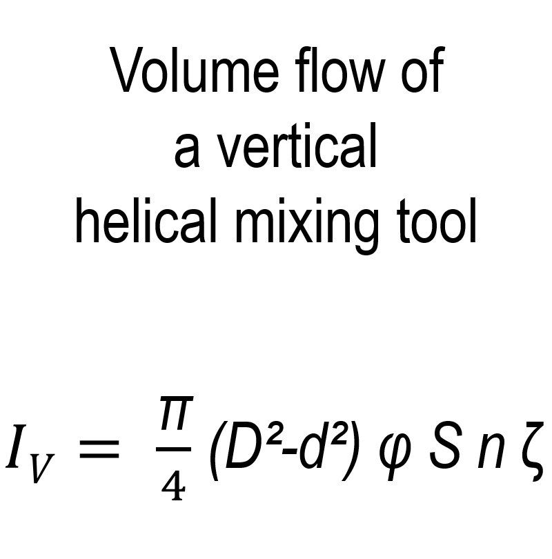
amixon® mixers mix three-dimensionally and produce ideal mixing qualities that cannot be improved in practice. This is achieved by the mixing spiral conveying the mix upwards without any dead space and gravity allowing the mix to flow downwards. The product current Iv can be described approximately as follows.
Iv = A · v_(ax) = (π/4) · (D² - d²) · φ · S · n · ζ
- Iv: Conveying capacity of a vertical mixing spiral
- D/ d: Outer/inner diameter of the spiral
- φ: Filling degree
- S: Pitch of the spiral
- n: Rotational frequency
- ζ: Speed coefficient
In this respect, the specific mixing capacity of amixon® mixers is always the same regardless of the size, provided that the geometric ratios are congruent.
amixon® has various synthesis reactors/vacuum mixing dryers in Paderborn. Some have a conical mixing chamber. Some have a flat bottom.

Worm conveyor mixer.
amixon® mixers mix three-dimensionally and produce ideal mixing qualities that cannot be improved in practice. This is achieved by the mixing spiral conveying the mix upwards without any dead space and gravity allowing the mix to flow downwards. The product current Iv can be described approximately as follows.
Iv = A · v_(ax) = (π/4) · (D² - d²) · φ · S · n · ζ
- Iv: Conveying capacity of a vertical mixing spiral
- D/ d: Outer/inner diameter of the spiral
- φ: Filling degree
- S: Pitch of the spiral
- n: Rotational frequency
- ζ: Speed coefficient
In this respect, the specific mixing capacity of amixon® mixers is always the same regardless of the size, provided that the geometric ratios are congruent.
amixon® has various synthesis reactors/vacuum mixing dryers in Paderborn. Some have a conical mixing chamber. Some have a flat bottom.
Worm conveyor mixer.
Are there any special features of processes that take place at high temperatures and high pressures?

amixon® technical center.
Tests can also be carried out under extreme process conditions in the amixon® technical center:
- System pressure in the process area up to 25 bar overpressure: The thicker container walls influence the heat transfer. On the other hand, the temperatures in the process area can be changed extremely quickly by changing the system pressure. If the system pressure in the process area is increased, gas-solid reactions, for example, can be favoured. For example, diffusion processes ....
- Heating up to 350°C: Conventional polymer seals fail when temperatures permanently exceed 240 °C. Then only metallic sealing systems or graphite gaskets can be used.
- Fine vacuum of 1 mbar absolute: Such absolute pressure requires the apparatus and all communicating connecting lines to be extremely tight. This applies in particular to the sealing of the agitator shaft.
How can the process of vacuum mixed drying be illustrated?
The drying process of a test run can be represented as a diagram as shown here. The time is plotted on the abscissa. Various physical quantities are plotted on the ordinate axis:
- the system pressure in the process chamber,
- the mass of the evaporated liquid,
- the temperature of the mass to be dried and
- the temperatures of the heat transfer medium in the flow and return.
The vacuum mixed dryer is usually filled with the maximum batch volume before the drying process begins. As a rule, the volume of the mixture decreases as drying progresses.
In rare cases, the filling volume remains constant, although the mix becomes drier and lighter. In very rare exceptional cases, there may even be an increase in volume during drying. This increase in volume must be taken into account, as the mixers/dryers must not be overfilled.
How does the heat transfer surface change as the filling level decreases?

View from above into a 20 m³ amixon® reactor
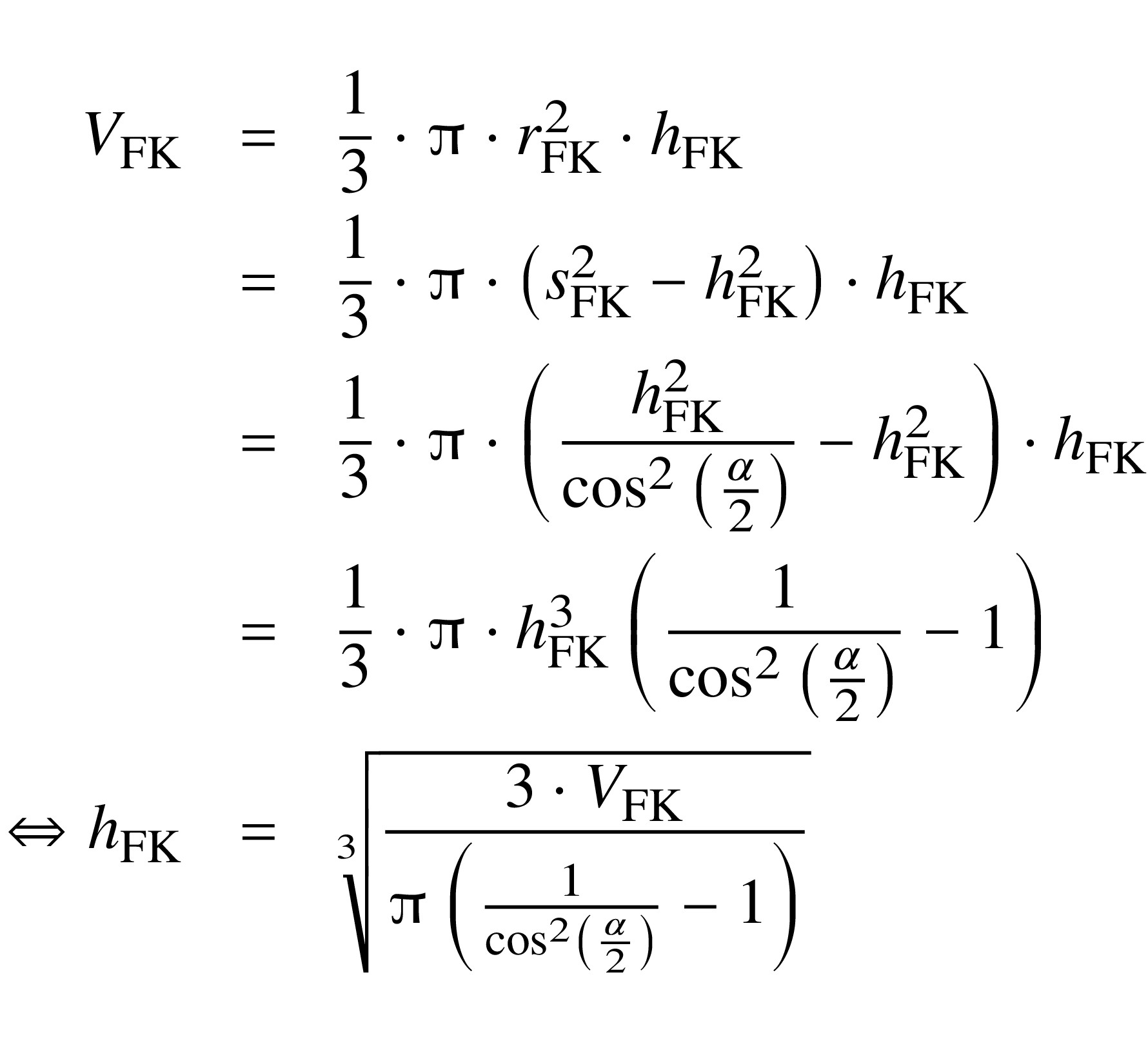
The heat transfer area of the vacuum dryer varies with the fill level. In this case, the mixing chamber consists of a cone topped by a cylinder. The following derivation calculates the heat transfer area for the case where the fill volume is smaller than the conical section of the mixing dryer.
Filling volume of the cone:
V_FK= (1/3) · π · h_(FK)^3 · (1/(cos^2(α/2)) - 1)
First, the filling height hFK in the cone is calculated:
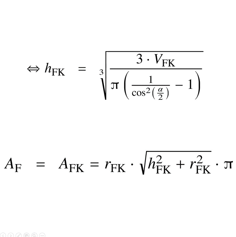
h_(FK) = ³√(3 · V_(FK)/(π · (1/(cos^2(α/2)) - 1)))
The heat-transfer surface area in the cone AF is only the area in contact with the mixture.
A_F = A_(FK) = r_(FK) · √(h_(FK)^2 + r_(FK)^2) · π
If the filling level in the mixing dryer changes during the drying process, the contact area of the tempered mixing tool also changes. This situation cannot be described as a closed function. amixon® calculates the heat exchange area of the mixing tool in the CAD system for various filling levels. The data is recorded in tabular form and interpolated.
View from above into a 20 m³ amixon® reactor
The heat transfer area of the vacuum dryer varies with the fill level. In this case, the mixing chamber consists of a cone topped by a cylinder. The following derivation calculates the heat transfer area for the case where the fill volume is smaller than the conical section of the mixing dryer.
Filling volume of the cone:
V_FK= (1/3) · π · h_(FK)^3 · (1/(cos^2(α/2)) - 1)
First, the filling height hFK in the cone is calculated:
h_(FK) = ³√(3 · V_(FK)/(π · (1/(cos^2(α/2)) - 1)))
The heat-transfer surface area in the cone AF is only the area in contact with the mixture.
A_F = A_(FK) = r_(FK) · √(h_(FK)^2 + r_(FK)^2) · π
If the filling level in the mixing dryer changes during the drying process, the contact area of the tempered mixing tool also changes. This situation cannot be described as a closed function. amixon® calculates the heat exchange area of the mixing tool in the CAD system for various filling levels. The data is recorded in tabular form and interpolated.
What is the heat requirement if the vacuum mixing dryer is significantly larger than the pilot plant?
Two indices are introduced below: ‘R’ (reference) for the pilot plant and ‘T’ (target) for the industrial-scale plant. The drying time is the time from the start of evaporation to the end of evaporation. The following idealised conditions are assumed:
- The process conditions in the test apparatus are identical to those in the industrial-scale apparatus.
- Evaporation takes place at a constant temperature.
- Evaporation takes place at constant system pressure.
- The heat transfer coefficient is the same in both apparatuses.
- The average temperature difference between the heating medium and the mixture is the same.
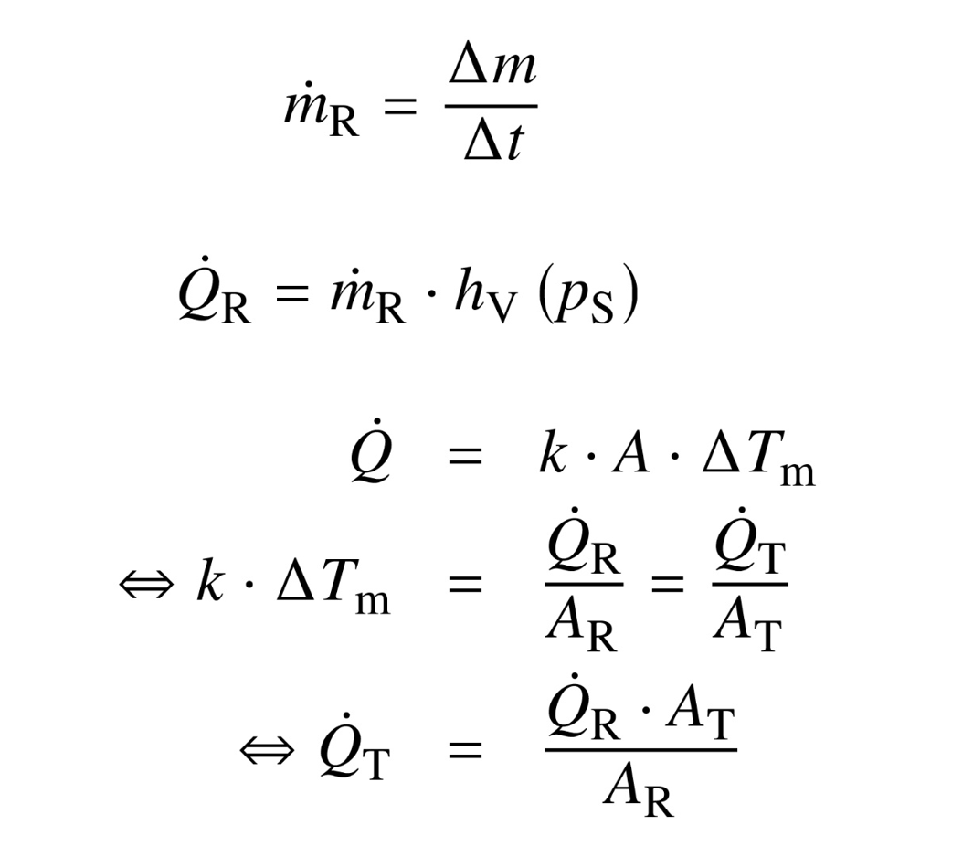
The evaporation rate is calculated from the evaporated mass Δm and the time Δt required for this during the phase of maximum evaporation in the reference measurement:
ṁ_R = Δm/Δt
Using the evaporation enthalpy h_V at the saturated vapour pressure p_S from the empirical equation, the heat flux required for evaporation in the reference apparatus can be determined:
Q̇_R = ṁ_R · h_V (p_S)
The heat flux through the heated contact area A of the target apparatus can thus be calculated as follows:
Q̇_T = (Q̇_R · A_T)/A_R
Two indices are introduced below: ‘R’ (reference) for the pilot plant and ‘T’ (target) for the industrial-scale plant. The drying time is the time from the start of evaporation to the end of evaporation. The following idealised conditions are assumed:
- The process conditions in the test apparatus are identical to those in the industrial-scale apparatus.
- Evaporation takes place at a constant temperature.
- Evaporation takes place at constant system pressure.
- The heat transfer coefficient is the same in both apparatuses.
- The average temperature difference between the heating medium and the mixture is the same.
The evaporation rate is calculated from the evaporated mass Δm and the time Δt required for this during the phase of maximum evaporation in the reference measurement:
ṁ_R = Δm/Δt
Using the evaporation enthalpy h_V at the saturated vapour pressure p_S from the empirical equation, the heat flux required for evaporation in the reference apparatus can be determined:
Q̇_R = ṁ_R · h_V (p_S)
The heat flux through the heated contact area A of the target apparatus can thus be calculated as follows:
Q̇_T = (Q̇_R · A_T)/A_R
How long does the drying process take in the large-scale plant?
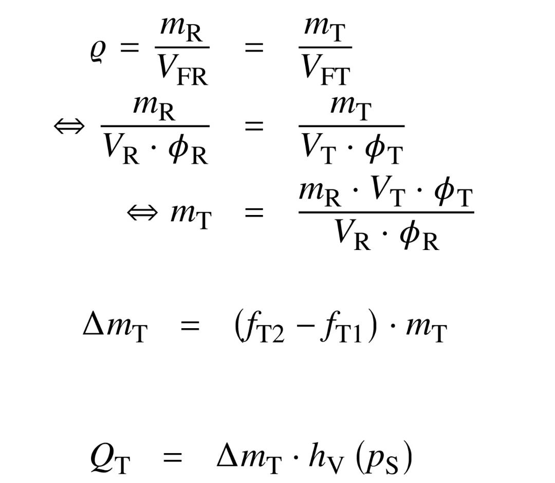
The mass evaporated over the entire drying period is:
Δm_T = (f_(T2) - f_(T1)) · m_T
where f_(T1) and f_(T2) denote the moisture content of the product at the start and end of the drying phase.
The evaporation rate is calculated from the mass evaporated Δm and the time required for this Δt during the phase of maximum evaporation in the reference measurement:
ṁ_R = Δm/Δt
Using the evaporation enthalpy h_V at the saturated vapour pressure p_S from the empirical equation, the heat flux required for evaporation in the reference apparatus can be determined:
Q̇_R = ṁ_R · h_V(p_S)
The heat flux through the heated contact area A of the target apparatus can thus be calculated as follows:
Q̇_T = (Q̇_R · A_T)/A_R = Q_T = Δm_T · h_V(p_S)
Using these values, the drying time in the target apparatus can be calculated:
Δt_T = Q_T/Q̇_T
What size should the heating system for the large dryer be?
The following diagram shows the individual consumption points. Each consumer must be supplied with sufficient heat energy based on the calculated requirements. The design factor S is used to calculate the heat flow in the heating system. This is based on the heat flow Qvap required for evaporation.
The design factor S is used to calculate the heat flow in the heating system based on the heat flow Q̇_(vap) required for evaporation:
Q̇_(heat) = -Q̇_(vap) · S
This gives the mass flow of the heat transfer medium:
ṁ_(heat) = (-Q̇_(vap) · S)/(c_p · (T_(2,heat) - T_(1,heat)))
The mass flow rate of the heat transfer medium Qvap is determined by the specific heat capacity cp, the inlet temperature of the heat transfer medium T1,heat and the outlet temperature of the heat transfer medium T2,heat. The thermal fluid must be distributed in such a way that all consumers are adequately supplied. This means that all areas of the process chamber must be heated evenly. Condensation must be avoided. The moist material must be heated to the extent that steam energy is removed. The mixed material temperature corresponds to the evaporation temperature of the adjacent vacuum.
A 16 m³ vacuum mixing dryer from amixon®.
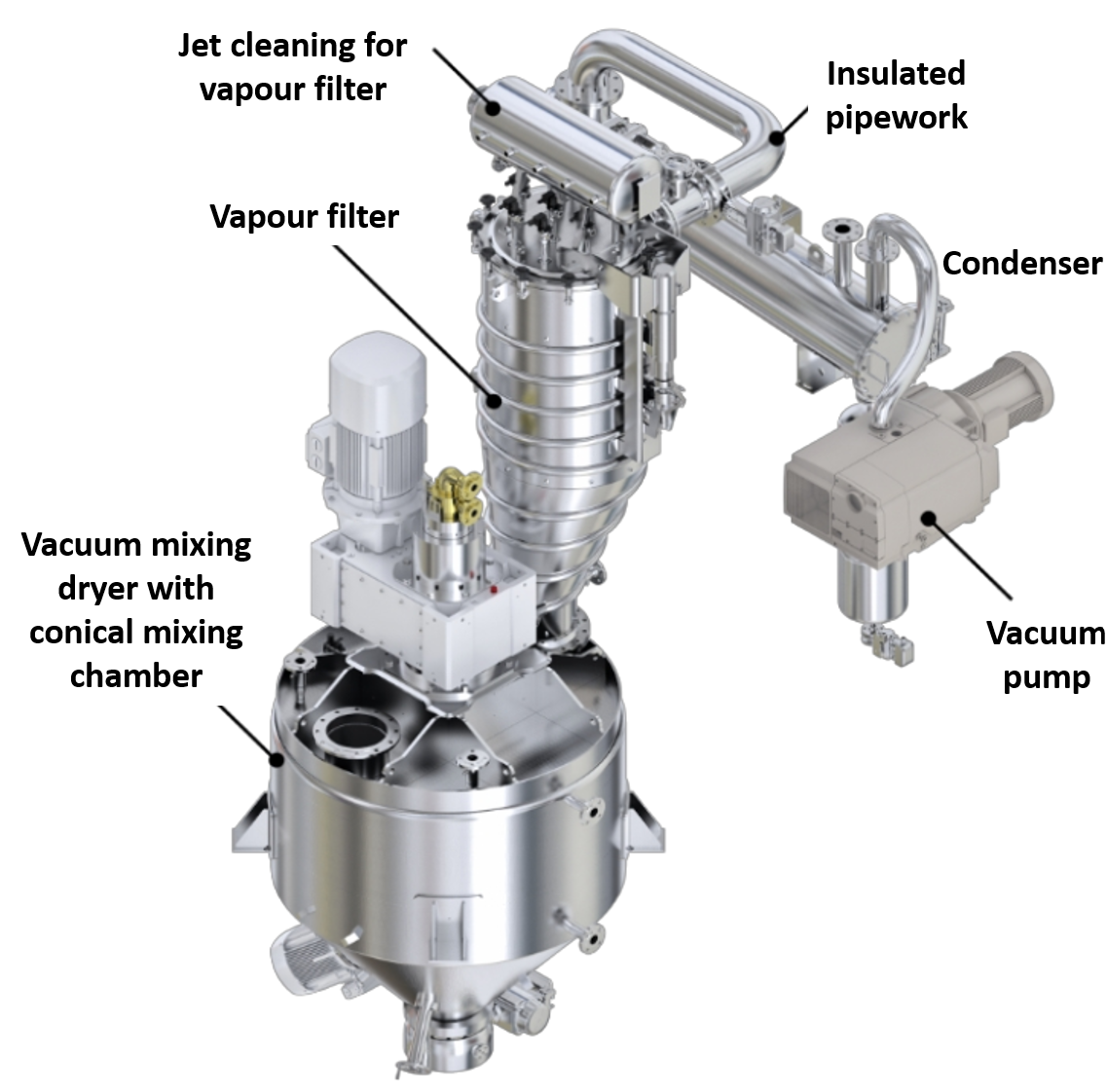
What size should the vapour filter for the large dryer be?
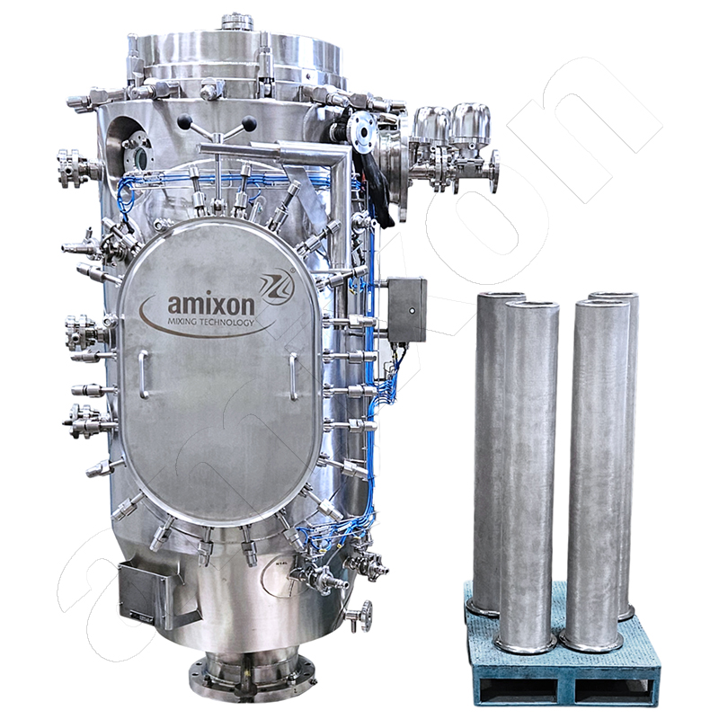
Vapour filter in pharmaceutical design. 4 metal filter cartridges. Side mounting.
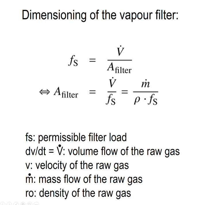
A_(filter) = V̇/f_S = ṁ/(ρ · f_S)
- Estimation of the required filter area based on the permissible filter load fs
- Using the volume flow rate dV/dt, the mass flow rate dm/dt and the density ρ of the vapour.
- The velocity of the dust-laden raw gas v is
- The filter area load fs is defined in the unit [m³/h/m²].
The vapour velocity is calculated in the inlet and outlet pipes as follows:
V̇ = A_(pipe) · v = (d^2/4) · π · v ; v = (4 · V̇)/(d^2 · π)
Vapour filter in pharmaceutical design. 4 metal filter cartridges. Side mounting.
A_(filter) = V̇/f_S = ṁ/(ρ · f_S)
- Estimation of the required filter area based on the permissible filter load fs
- Using the volume flow rate dV/dt, the mass flow rate dm/dt and the density ρ of the vapour.
- The velocity of the dust-laden raw gas v is
- The filter area load fs is defined in the unit [m³/h/m²].
The vapour velocity is calculated in the inlet and outlet pipes as follows:
V̇ = A_(pipe) · v = (d^2/4) · π · v ; v = (4 · V̇)/(d^2 · π)
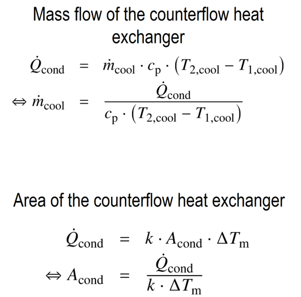
What size condenser is required for the large dryer?
Q̇_(cond) = Q̇_(vap)
- The vapour is cleaned in the vapour filter and condensed in the condenser.
- In this process, the heat flux “Q̇cond” must be removed. This is achieved by the cooled condensation surface “Acond”.
- Taking into account the heat transfer coefficient and the mean temperature difference, the mass flow rate of the cooling medium “ṁcool” is calculated:
- When determining the “K” value, the design of the condenser and the expected fouling factor must be taken into account.
For the condenser surface area of the heat transfer in a counter-flow heat exchanger, the following applies:
Q̇_(cond) = k · A_(cond) · ΔT_m
A_(cond) = Q̇_(cond)/(k · ΔT_m)
The mass flow rate of the cooling fluid is given by:
Q̇_(cond) = ṁ_(cool) · c_p · (T_(2,cool) - T_(1,cool))
ṁ_(cool) = Q̇_(cond)/(c_p · (T_(2,cool) - T_(1,cool)))

Exemplary: Rohrbündelkondensator K. Ley GmbH & Co. KG
Q̇_(cond) = Q̇_(vap)
- The vapour is cleaned in the vapour filter and condensed in the condenser.
- In this process, the heat flux “Q̇cond” must be removed. This is achieved by the cooled condensation surface “Acond”.
- Taking into account the heat transfer coefficient and the mean temperature difference, the mass flow rate of the cooling medium “ṁcool” is calculated:
- When determining the “K” value, the design of the condenser and the expected fouling factor must be taken into account.
For the condenser surface area of the heat transfer in a counter-flow heat exchanger, the following applies:
Q̇_(cond) = k · A_(cond) · ΔT_m
A_(cond) = Q̇_(cond)/(k · ΔT_m)
The mass flow rate of the cooling fluid is given by:
Q̇_(cond) = ṁ_(cool) · c_p · (T_(2,cool) - T_(1,cool))
ṁ_(cool) = Q̇_(cond)/(c_p · (T_(2,cool) - T_(1,cool)))
Exemplary: Rohrbündelkondensator K. Ley GmbH & Co. KG
A straight line idealises the mass flow of the condensate
What is the intention when the measured condensate mass flow is averaged by a straight line? This rough approximation allows a comparison with a continuously operated parallel flow heat exchanger. The effects of changing process parameters can be calculated with a very good approximation..

This corresponds to the first drying stage after product heating.
What is the intention when the measured condensate mass flow is averaged by a straight line? This rough approximation allows a comparison with a continuously operated parallel flow heat exchanger. The effects of changing process parameters can be calculated with a very good approximation..
This corresponds to the first drying stage after product heating.
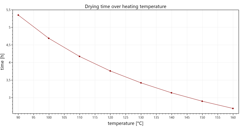
How long does the drying process take in the large-scale plant if the temperature of the thermal fluid is altered?
Heat transfer during evaporation is similar to that in a co-current heat exchanger. This results in the following for the mean temperature difference of the heat transfer:
ΔT_m = ((T_(2,heat) - T_(vap)) - (T_(1,heat) - T_(vap)))/ln((T_(2,heat) - T_(vap))/(T_(1,heat) - T_(vap)))
The planned large-scale drying plant can be operated with a warmer or a colder heat transfer medium. In this case, the drying time changes. These considerations are made by analogy with the operation of a “parallel-flow heat exchanger”. The value for “T2,heat” can only be determined numerically by iteration. This allows an interesting curve to be approximated. It enables the estimation of drying times at different temperatures of the heat transfer medium.
The modified drying time is thus calculated as:
Q̇_(vap) = Q_(vap)/Δt_(dry)
Δt_(dry) = Q_(vap)/Q̇_(vap)
Why does it take longer to cool dry powder than to heat moist powder?
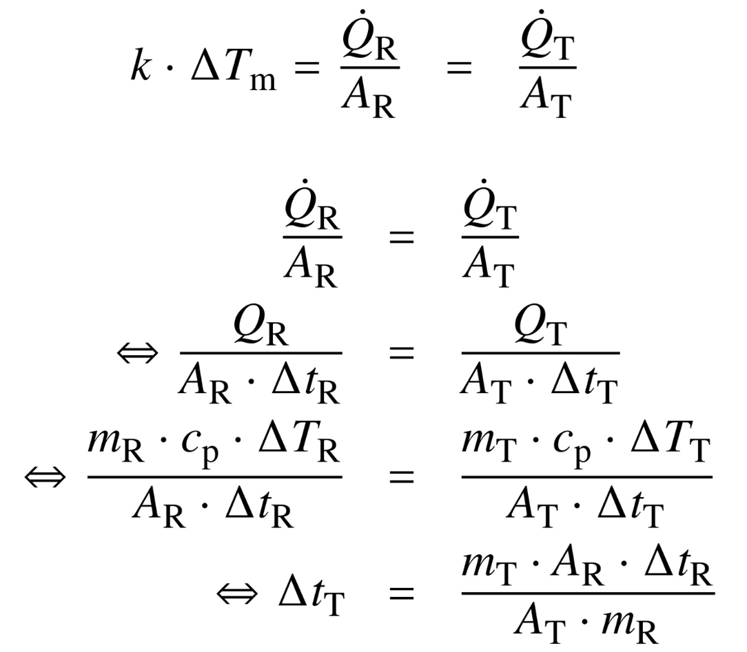
When estimating the cooling time “Δ tT”, it is assumed that the same conditions prevail in the pilot plant and in the industrial dryer. This applies both to the heat transfer coefficient and to the average temperature difference between the heat transfer medium and the product temperature. The product in the industrial plant is to be cooled to the same final temperature as that tested in the pilot plant.
Analogous to the calculation of the drying time in the target apparatus, the following applies to heat transfer during cooling:
k · ΔT_m = Q̇_R/A_R = Q̇_T/A_T
The cooling time can thus be calculated using the product masses in the reference and target apparatus, m_R and m_T, the contact areas A_R and A_T, and the cooling time of the reference apparatus, Δt_R:
Q̇_R/A_R = Q̇_T/A_T
(m_R · c_p · ΔT_R)/(A_R · Δt_R) = (m_T · c_p · ΔT_T)/(A_T · Δt_T)
Δt_T = (m_T · A_R · Δt_R)/(A_T · m_R)
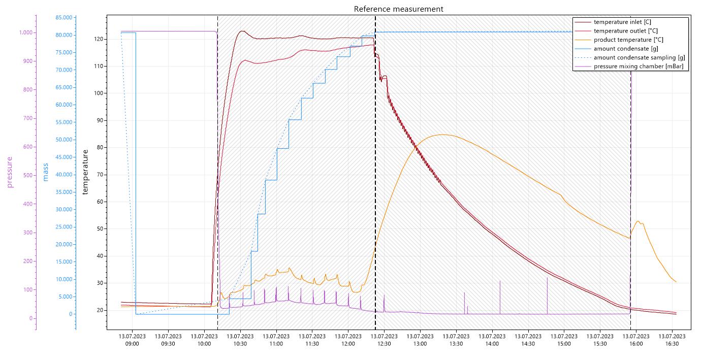
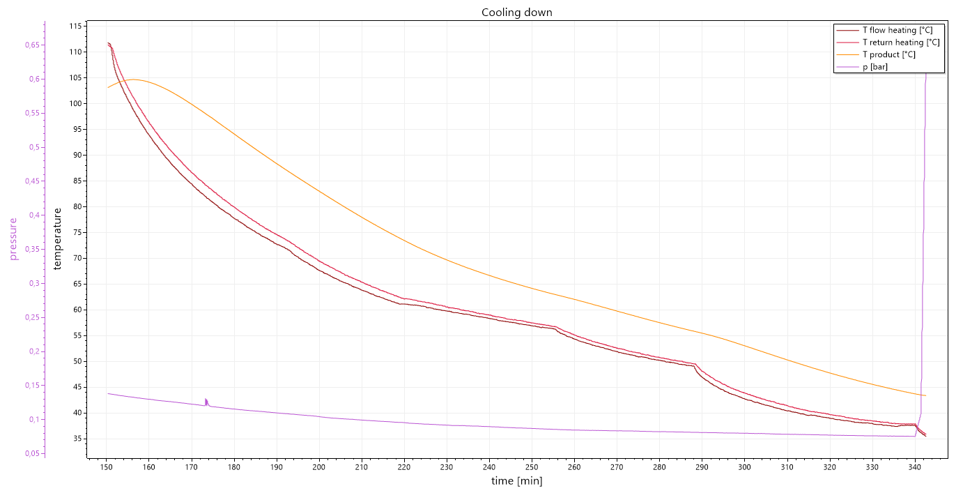
What is striking about the mix cooling in this diagram?
A typical cooling curve is shown below. The cooling of dry powder takes longer than the heating of wet powder. There are two explanations for this:
- A liquid conducts heat much better than most solids.
- The liquid film surrounding a moist particle can wet the heat transfer surface. This promotes heat transfer. In contrast, a dry particle only touches the tempered surface at a few points.
In this case, the dryer was heated with a very high temperature difference. The thermal oil was initially approx. 120°C hot. In this case, the entire thermal oil storage tank must first be cooled in the system flow. This results in the cooling of the drying powder with a pronounced hysteresis.
If water were used as the heat transfer medium, the cooling process would be accelerated.
Do you have any further questions? .... You can contact us at any time.
© Copyright by amixon GmbH